ESCOMATIC Automatic Lathe Cam System Design Guide
ESCOMATIC Automatic Lathe Cam System Design Guide
In the field of precision machining, the ESCOMATIC automatic lathe is renowned for its exceptional accuracy and efficiency. Its core advantage lies in its meticulously designed cam system. This article provides an in-depth analysis of the system's design principles and implementation methods.
ESCO-Type CNC Technology Applications
💡 "With the development of CNC technology, our ESCOMATIC-type Y2-CNC lathe represents a technological innovation in ESCOMATIC automatic lathes. Unlike traditional cam-driven systems, the Y2-CNC uses servo systems to precisely control material and tool feeding, completely eliminating the need to design complex cam systems. This CNC solution not only improves machining accuracy and repeatability, but more importantly, is extremely user-friendly for operators and programmers, significantly reducing learning costs and operational complexity. Whether beginners or experienced technicians, everyone can quickly master Y2-CNC operation and achieve efficient precision machining. For inquiries: +86-139 1634 2943"
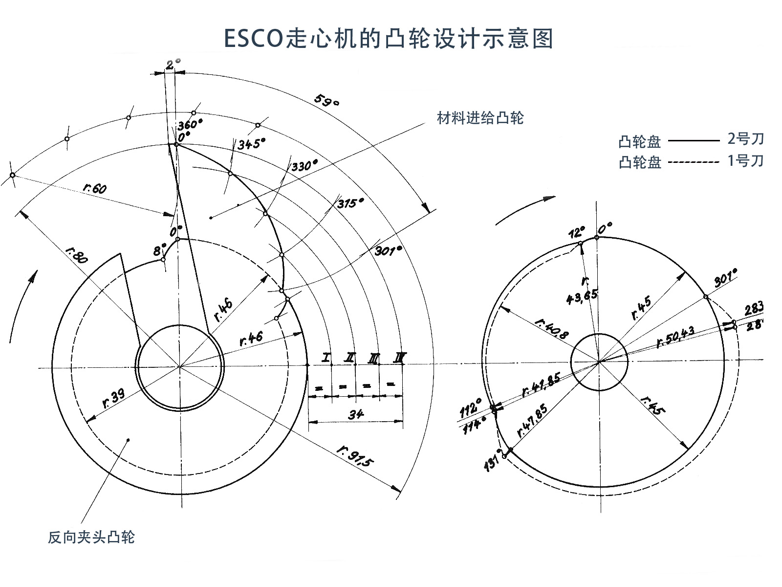
Figure 1: ESCOMATIC automatic lathe cam system design diagram - Showing the precise coordination between material feed cam, counter-collet cam, and tool cams
I. Material Feed Cam
1. Basic Parameters
- Outer diameter: Ø160 mm
- Keyway width: 25 mm (radial arrangement)
- Zero position radius: 80 mm (360° position)
- Feed start point: 301° (radius 46 mm)
- Lift curve range: 301°→360° (lift 34 mm)
2. Curve Drawing Method
The material feed cam design employs a segmented division method, dividing the 301°-360° interval into four equal parts. Through lever arc positioning and lift mapping, it ensures smooth feeding motion. The specific steps include:
1)Segment division: Divide 301°-360° interval into four equal parts (division points: 315°, 330°, 345°)
2)Lever arc positioning: Create concentric circles with 91.5 mm radius from cam center
3)Lift mapping: Divide 34 mm lift into four equal parts
4)Smooth connection: Connect intersection points to form uniform rising curve
II. Counter-Collet Cam
The counter-collet cam is responsible for workpiece clamping and release, with the following action logic:
| Cam Angle | Action | Radius Change |
|---|---|---|
| 0°→8° | Collet Close | 46 mm → 39 mm |
| 8°→296° | Maintain Closed | Constant 39 mm |
| 296°→301° | Prepare Open | 39 mm → 46 mm |
| 301°→360° | Maintain Open | Constant 46 mm |
III. Tool Cam Design Specifications
1. General Rules
- Lift ratio: 3:1 (core law)
- Zero position radius: 45 mm (unified reference)
- Zero position state: Tool tip 0.5 mm from workpiece surface
2. Tool 2 Cam (Finishing/Chamfering)
- Chamfering stage (0°→12°): Working stroke Ø3.5 → Ø2.6 mm
- Rounding (12°→112°): Lift 1.8 mm
- Finishing section (112°→114°): Constant radius 41.85 mm
- Retraction (114°→360°): Uniform rise to zero position radius 45 mm
3. Tool 1 Cam (Cutting)
- Cutting end point (283°): Over-center cut 0.06 mm
- Retraction curve (283°→302°): Uniform decrease to 45 mm
- Cutting start point (131°): Cutting depth 0.86 mm
IV. Drawing and Manufacturing Points
Material Selection
- Cam base: 20CrMnTi alloy steel
- Surface treatment: Carburizing and quenching HRC58-62
Tolerance Standards
- Radius tolerance: ±0.01 mm
- Angular division: ±0.1°
Dynamic Verification
Simulate cam group motion in CAM software, focusing on:
-
Whether Tool 1 collides with collet during retraction
-
Synchronization of material feed and collet opening
Conclusion
The ESCOMATIC automatic lathe cam system design embodies the essence of precision mechanical design. Through a 3:1 lift ratio and strict phase synchronization, it achieves ±0.005mm dimensional stability in micro-shaft machining with diameters ≤4mm. Electrical Discharge Machining (EDM) is recommended for manufacturing cam profiles to ensure surface smoothness (Ra≤0.4μm).
In practical applications, special attention must be paid to dynamic verification and actual debugging to ensure that the cam follower trajectory deviation from the theoretical curve does not exceed 0.02 mm, which is crucial for maintaining machining accuracy.