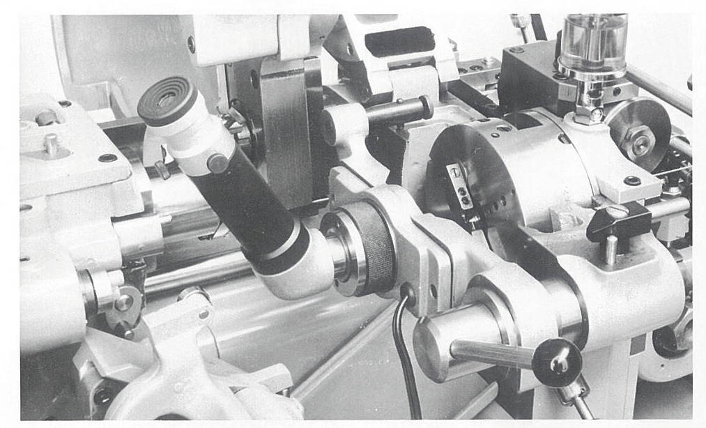
The centering microscope is an indispensable precision tool in ESCOMATIC automatic lathes. The smaller the diameter of the workpiece to be machined, the more crucial it becomes to ensure the cutting edges are precisely centered. This tool is essential for achieving the key advantage of the ESCOMATIC system: burr-free cutting. While the holding collet is important, it is absolutely necessary that the cutting edge of the parting tool works exactly in the center of the guide bush bore.
💡 Our CNC ESCOMATIC Y2-CNC Automatic Lathe also uses a centering microscope for tool alignment, but with more convenient operation. For example, tool compensation for cutting tools can be directly added on the control screen, easily achieving burr-free cutting, significantly improving machining efficiency and precision. Additionally, we offer well-maintained used cam-type ESCOMATIC machines that have been professionally serviced and calibrated for stable and reliable performance.
Functions and Background of the Centering Microscope
The centering microscope plays a crucial role in ESCOMATIC automatic lathe machining:
- Core Function: Ensures precise alignment of lathe tool cutting edges with the guide bush bore center
- Application Scenarios: Essential for small-diameter workpieces and critical for achieving burr-free cutting operations
Equipment Structure and Principles
Microscope Components
| Component |
Specification |
Function |
| Eyepiece (A) |
20x magnification |
Built-in crosshair reticle for precise alignment |
| Crosshair Reticle (g) |
Concentric rings (C) |
Center intersection point corresponds to guide bush bore axis |
| Light Source |
Two 6V incandescent lamps |
Illuminates field of view, adapted to 110/220V through transformer |
Adjustment Mechanisms
| Mechanism |
Control |
Purpose |
| Objective Axial |
Knurled nut (f) |
Adjusts for clear guide bush bore contour display |
| Eyepiece Focus |
Rotating eyepiece (A) |
Achieves sharp focus of crosshairs and concentric rings |
| Concentric Calibration |
Four radial screws |
Aligns concentric rings with guide bush bore |
Tool Alignment Operation Process
Step 1: Microscope Calibration
| Step |
Action |
Purpose |
| 1 |
Turn on illumination |
Provides clear field of view |
| 2 |
Adjust knurled nut (f) |
Makes guide bush bore clearly visible |
| 3 |
Rotate eyepiece (A) |
Focuses crosshair and concentric rings sharply |
| 4 |
Adjust four radial screws |
Aligns concentric rings with guide bush bore |
Step 2: Tool 1 (Parting Tool) Alignment
| Step |
Action |
Purpose |
| 1 |
Move Tool 1 to position |
Places tool in front of guide bush |
| 2 |
Adjust knurled nut (f) |
Shows clear cutting edge contour |
| 3 |
Fine-tune with screw (g) |
Aligns cutting edge with crosshair intersection |
| 4 |
Tighten fixing screws (4) |
Secures tool in position |
Step 3: Tool 2 Alignment (for Multi-tool Machining)
| Step |
Action |
Purpose |
| 1 |
Unlock and rotate tool holder |
Positions for Tool 2 alignment |
| 2 |
Recalibrate microscope |
Ensures accurate alignment after rotation |
| 3 |
Adjust Tool 2 position |
Aligns with crosshair intersection |
Special Case Handling
| Condition |
Action |
Purpose |
| Tool 2 cannot align directly |
Rotate cam shaft manually |
Positions tool at lowest cam point |
| Cutting edge alignment |
Adjust micrometer screw (49) |
Aligns with crosshair intersection |
| Return to working position |
Use micrometer screw (49) |
Restores original machining position |
Key Considerations
Lighting and Focusing
- Ensure even illumination for clear field of view
- Coordinate objective and eyepiece adjustment: first clear guide bush bore display, then focus crosshair
Calibration Frequency
- Recalibrate microscope after tool changes or tool holder rotation
- Regularly check calibration status to ensure machining accuracy
Tool Position Compensation
- Cutting edge located in front of guide bush front end plane, use objective adjustment to display contour
- Note impact of tool wear on calibration
Advantages and Application Scenarios
High Precision
- 20x magnification ensures micron-level alignment accuracy
- Essential for achieving burr-free cutting
- Critical for small-diameter workpiece machining
Efficiency
- Quick tool switching and calibration
- Reduces setup time
- Increases production efficiency
Flexibility
- Suitable for small-diameter workpieces
- Adapts to different machining requirements
Summary
The centering microscope combines optical magnification with mechanical adjustment to precisely position tool cutting edges to the guide bush bore axis, solving the core alignment challenge in small workpiece machining. Its operation logic emphasizes "calibrate equipment first, then adjust tools," and through modular design (such as rotatable tool holder) adapts to multi-tool scenarios, making it a key auxiliary tool for precision ESCOMATIC automatic lathes. Mastering the correct use of the centering microscope is crucial for achieving burr-free cutting and maintaining high machining accuracy.